Phase Separation Technology
Let’s review some important aspects of the interesting phase separation technology:
The Role of Multiphase Separators
Multiphase Separator Terminology
The very first multiphase separator
The wide variety of separator designs
Phase Separation Zones
Operating Pressures and Capacities
Separator Internals
Common Operational Difficulties
CFD as a Separator Modeling Method
CFD Simulation of Multiphase Separators
The Role of Multiphase Separators
Multiphase
separators
are
one
of
the
most
prevalent
unit
operations
in
any
chemical
process.
Once
a
crude
oil
has
reached
the
surface,
the
main
purpose
of
the
surface
facilities
is
to
separate
the
produced
multiphase
stream
into
its
vapor
and
liquid
fractions.
Multiphase
separators
are
generally
the
first
process
equipment
in
an
oil
production
platform,
and
their
efficiency
influences
the
performance
of
all
downstream
equipment,
such
as
heaters,
compressors,
and
distillation
columns.
Thus,
oilfield
separators
play
a
key
role
in
the
production
capacity
of
entire
facility,
and
a
properly
sized
primary
multiphase
separator
can
increase
the
capacity
of
the
entire
facility.
In
some
oilfields,
water
(brine)
is
not
produced
together
with
oil,
and
hence
only
the
gas
and
the
oil
need
to
be
separated
(two-phase
separation).
However,
usually,
three-phase
separation
of
oil,
water,
and
gas
is
required
in
order
to
prepare
the
produced
multiphase
fluid
for
downstream
processing.
Multiphase Separator Terminology
Multiphase
separation
can
be
carried
out
through
various
oil
processing
equipment
with
the
specific
terminology
corresponding
to
each
system.
Hence,
it
is
worth
defining
the
most
important
multiphase
separators
in
the
oil
industry
before
proceeding.
The
conventional
oil
and
gas
separator,
which
is
normally
installed
on
a
production
facility
or
platform,
may
be
referred
to
as
“oil
and
gas
separator”,
“separator”,
“stage
separator”,
or
“trap”.
A
“knockout
vessel”
is
used
to
remove
either
water
or
all
liquid
from
the
well
fluid
flow.
An
“expansion
vessel”
is
the
first
stage
separator
vessel
usually
operated
at
a
low
temperature.
A
“flash
chamber”
or
“flash
vessel”
normally
refers
to
a
conventional
oil
and
gas
separator
operated
at
low
pressure
as
the
second
or
third
stage
of
the
multistage
separation.
A
“gas
scrubber”
is
an
oil
and
gas
separator
with
a
high
gas
to
liquid
ratio.
In
a
“wet-type
gas
scrubber”,
dust,
rust,
and
other
impurities
of
the
gas
phase
are
washed
using
a
bath
of
oil
or
other
liquid,
and
the
gas
flows
through
a
demister
to
further
remove
liquid
droplets
from
the
gas
stream.
A
“dry-type
gas
scrubber”
or
“gas
filter”
is
equipped
with
demisters
and
other
coalescing
media
to
aid
in
the
removal
of
most
of
the
liquid
from
a
gas
stream.
The very first multiphase separator
The
original
phase
separator
was
inclined,
very
long,
and
without
any
internal
separating
aids.
During
the
retention
time
(around
one
minute),
the
gas
and
oil
underwent
a
very
limited
separation.
Sir
Stephen
Gibson
designed
this
simple
phase
separator
and
also
the
multi-stage
separation
process.
He
was
the
first
to
put
this
process
into
operation
in
1930
at
the
Haft-Kel
oilfield in Iran (Skelton, 1977).
The wide variety of separator designs
A
wide
variety
of
separator
designs
and
configurations
for
multiphase
separators
in
both
vertical
and
horizontal
orientations
have
been
developed.
Various
parameters
such
as
space
and
operating
restrictions,
oilfield
variations,
potential
contaminants,
and
economic
evaluations
are
considered
in
the
design
of
a
multiphase
separation
system.
For
instance,
some
separators
may
be
equipped
with
special
impingement
internals
to
aid
the
separation
process.
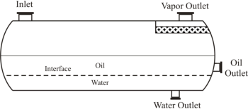
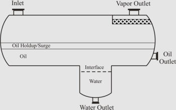
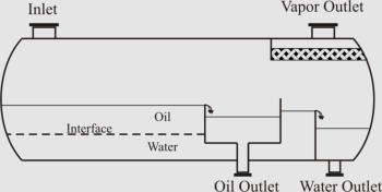
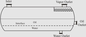
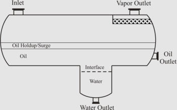
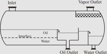
The
figure
below
shows
some
different
common
designs
composed
of
“simple”,
“boot”,
“weir”,
and
“bucket
and
weir”.
These
designs
offer
a
variety
of
methods
to
control
the
interface
level
in
horizontal
three-phase
separators.
“Simple”
design
separator
can
easily
be
adjusted
to
handle
unexpected
changes
in
oil
or
water
density
or
flow
rates
(Arnold
and
Stewart,
2008).
A
boot,
typically,
is
used
when
the
water
fraction
is
not
substantial
(less
than
15-20%
of
total
liquid
by
weight),
and
a
weir
is
used
if
the
water
fraction
is
substantial
(Monnery
and
Svrcek,
1994).
The
bucket
and
weir
design
is
usually
used
when
interface
level
control
is
difficult
either
in
heavy
oil
applications
or
because
of
emulsions or paraffin problems (Arnold and Stewart, 2008).
(
a
)
(
b)
(
c) (
d)
Different Common Designs of Horizontal Three-Phase Separators; (a) “Simple”, (b) “Boot”, (c)
“Weir”, and (d) “Bucket and Weir”.
Phase Separation Zones
In
spite
of
the
variety
of
design
configurations
proposed
for
multiphase
separators,
the
phase
separation
process
is
accomplished
in
three
zones:
The
first
zone,
primary
separation,
uses
an
inlet
diverter
so
that
an
abrupt
change
in
flow
direction
and
velocity
causes
the
largest
liquid
droplets
to
impinge
on
the
diverter
and
then
drop
by
gravity.
In
this
zone,
the
bulk
of
the
liquid
phase
is
separated
from
the
gas
phase.
In
the
next
zone,
secondary
separation
zone,
gravity
separation
of
fine
droplets
occurs
as
the
vapor
and
liquid
phases
flow
through
the
main
section
of
the
separator
at
relatively
low
velocities
and
little
turbulence,
and
the
liquid
droplets
settle
out
of
the
gas
stream
due
to
gravity.
The
liquid
collection
section
in
the
bottom
half
of
separator
provides
the
retention
time
required
for
entrained
gas
bubbles
or
other
liquid
droplets
to
join
their
corresponding
phases
because
of
gravity
and
buoyancy.
This
section
also
provides
the
holdup
and
surge
volumes
for
safe
and
smooth
operation
of
the
separator.
Gas
flows
above
the
liquid
phase
while
entrained
small
liquid
droplets
are
again
separated
by
gravity.
The
final
zone,
coalescing
media,
is
designed
for
mist
elimination
in
which
very
fine
droplets
that
could
not
be
separated
in
the
gravity
settling
zone
are
separated
by
passing
the
gas
stream
through
a
mist
eliminator.
In
this
zone,
vanes,
wire
mesh
pad,
or
coalescing
plates
may
be
used
to
provide
an
impingement
surface
for
very
fine
droplets to coalesce and form larger droplets which can be separated out of gas stream by gravity.
Phase Separation Zones
Operating Pressures and Capacities
The
operating
pressure
of
separators
may
vary
from
a
high
vacuum
to
around
35
MPa
(Smith,
1987)
and
their
capacities
may
range
from
a
few
hundred
barrels
per
day
to
100000
barrels
per
day
or
more
(Skelton,
1977).
As
the
operating
pressure
of
a
separator
increases,
the
density
difference
between
the
liquid
and
gas
phases
decreases.
Therefore,
it
is
desirable
to
operate
multiphase
separators
at
as
low
a
pressure
as
is
consistent
with
other
process
conditions
and
requirements.
Most multiphase separators operate in a pressure range of 138 kPa to 10340 kPa (Smith, 1987).
Separator Internals
The
modern
separator
designs
have
much
higher
capacities
than
the
original
type
and
are
very
short
in
length
due
to
internals
such
as
inlet
diverters,
controls,
flow-distributing
baffles,
and
mist
extractors
which
enhance
the
separator
efficiency.
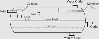
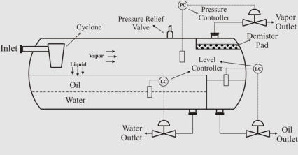
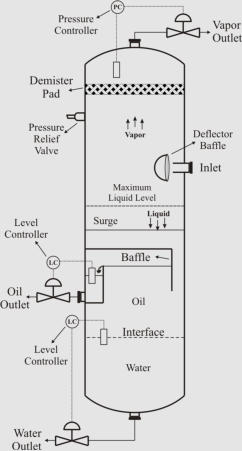
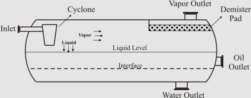
A
“weir”
design
horizontal
three-phase
separator
and
a
vertical
three-phase
separator,
both
with
the
installed
internals,
are
shown
in
the
Figures
below.
As
shown,
both
separators
are
equipped
with
inlet
diverters,
controls,
wire
mesh
demisters
and
pressure
relief
devices.
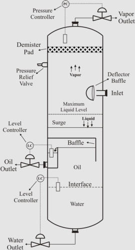
In
the
vertical
separator,
a
chimney
is
used
to
equalize
gas
pressure
between
the
lower
and
upper
sections
of
the
vessel.
Important
common
internals
are
explained as follows.
“Weir” Design Horizontal Three-Phase Separator with the Installed Internals.
Vertical Three-Phase Separator with the Installed Internals.
Inlet Diverters
Usually
a
deflector
baffle
or
a
cyclone
is
used
as
inlet
diverter
in
the
separator.
Deflector
baffles
come
in
various
shapes
and
can
be
installed
at
different
angles.
However,
hemisphere
or
conical
designs
are
preferred
because
they
cause
fewer
disturbances
than
plates
or
angle
iron
and
reduce
re-entrainment
and
emulsion
problems
(Arnold
and
Stewart,
2008).
Cyclone
diverters
are
increasingly
used
in
oil
production
facilities
as
they
promote
foam
breaking
and
mist
elimination
while
performing
the
bulk
gas-liquid
separation
in
the
inlet
zone
(Chin
et
al.,
2002).
Hence,
cyclone diverters can be used to increase the operating capacity of multiphase separators.
Controls
Separators
operate
at
a
predetermined
pressure
which
is
specified
by
economic
and
engineering
studies.
The
fixed
operating
pressure
in
a
separator
is
achieved
by
using
an
automatic
back
pressure
regulator
on
the
gas
outlet
line.
This
device
maintains
a
steady
operating
pressure
in
the
vessel.
The
liquid
level
controllers
and
liquid
outlet
control
valves
are
used
to
maintain
constant
oil
and
water
levels
in
the
separator.
Consequently,
the
operation
of
modern
separator
systems
is
completely automatic.
Mist Eliminators
Droplets
with
diameters
of
100
micron
and
larger
will
generally
settle
out
of
the
gas
stream
in
most
average-sized
separators.
However,
mist
eliminators
are
usually
required
to
remove
smaller
droplets
from
the
gas
phase
(Smith,
1987).
As
95%
of
droplets
entrained
in
the
gas
stream
can
be
separated
in
economically-sized
separators
without
coalescing
media,
the
efficiency
can
be
increased
to
around
100%
by
installing
mist
eliminators
(Walas,
1990;
Sinnott,
1997;
Arnold
and
Stewart,
2008).
These
coalescing
media
can
consist
of
a
series
of
vanes,
a
knitted
wire
mesh
pad,
or
cyclonic
passages
to
remove
the
very
fine
droplets
from
the
gas
phase
by
impingement
on
a
large
surface
area
where
they
collect
and
collide
with
adjacent
droplets.
The
mechanisms
used
in
various
mist
eliminators
are
gravity
separation,
impingement,
change
in
flow
direction
and
velocity,
centrifugal
force,
coalescence,
and
filtering
(Smith,
1987).
Mist
eliminators
can
be
of
many different designs exploiting one or more of these mechanisms.
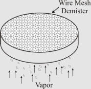
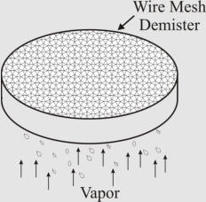
The
wire
mesh
pads,
shown
below,
are
made
of
knitted
wire
mesh
and
are
installed
by
a
lightweight
support
inside
separators.
Since
the
early
1950s,
the
wire
mesh
demisters
have
been
used
in
natural
gas
processing
with
the
main
use
of
removing
fine
droplets
ranging
from
10
to
100
micron
in
diameter
from
the
gas
stream
(Smith,
1987).
Generally,
high
separation
efficiencies
at
a
low
capital
and
maintenance
cost
are
experienced
from
using
standard
wire
mesh
demisters.
The
pressure
drop
is
a
function
of
the
entrainment
load,
the
mesh
pad
design,
and
gas
velocity
but
does
not
usually
exceed
295
Pa
(Lyons
and
Plisga,
2005).
Although
pad
thicknesses
up
to
0.9
m
have
been
used,
a
pad
thickness
of
0.10
m
to
0.15
m
is
normally
sufficient
for
most
separator
applications
(Gerunda,
1981;
Walas,
1990;
Lyons
and
Plisga,
2005).
However,
the
“fouling”
tendency
of
wire
mesh
demisters
may
restrict
their
applications
to
gas
scrubbers
(Smith,
1987).
In
fact,
knitted
wire
mesh
may
foul
or
plug
from
paraffin
deposition
and
other
impurities
and
thus
reduce
separation
efficiency
dramatically
after
a
short
period
of
service.
In
such
cases,
vane-type
or centrifugal demisters are used.
Wire Mesh Pad Mist Eliminator.
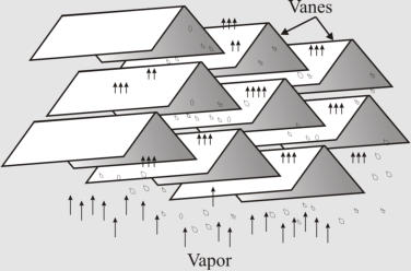
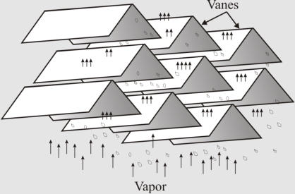
Vane-type
demisters,
shown
below,
are
widely
used
in
oil
and
gas
separators.
The
separation
mechanisms
used
in
most
of
vane-type
demisters
are
impingement,
change
in
flow
direction
and
velocity,
and
coalescence.
Vane-type
demisters
use
the
inertia
of
the
liquid
droplets
in
the
gas
stream
to
collect
a
film
of
liquid
on
the
vane
surface.
Vane-type
demisters
are
inexpensive
and
usually
will
not
plug
or
foul
with
paraffin
or
other
contaminants,
hence,
providing
a
good
separation
performance
under
widely
changing
field
conditions
(Smith,
1987).
Pressure
drop
across the vane-type demisters are very low, ranging from 250 Pa to 1 kPa (Smith, 1987).
Vane-Type Mist Eliminator.
Common Operational Difficulties
The
most
common
factors
which
can
reduce
separator
performance
are
very
high
or
very
low
liquid
level,
level
control
failure,
improper
design,
damaged
vessel
internals,
foam,
vortex
formation
in
liquid
outlet
zones,
plugged
liquid
outlets,
and
exceeding
the
design
capacity
of
the
vessel (Arnold and Stewart, 2008).
The
common
approaches
used
for
improving
the
separator
performance
in
difficult
cases,
as
proposed
by
Blezard
et
al.
(2000),
are
increasing
droplet
size
of
dispersed
phase
(e.g.,
by
promoting
coalescence),
inducing
a
high
acceleration
on
droplets
(e.g.,
by
using
centrifugal
force),
increasing
the
difference
between
fluid
densities
(e.g.,
by
introducing
diluents),
and
decreasing
the
viscosity
of
the
liquid
phases
(e.g.,
by
heating).
Some
of
these
approaches
may
be
combined
to
overcome
a
difficult
separation
task.
In
the
following,
some
different
measures
taken
for
operating
foamy,
emulsified, or contaminated crude oils are outlined.
Foamy
crude
oils
hinder
liquid
level
control
and
also
reduce
the
separation
space
of
the
separator.
To
improve
the
separator
performance,
it
is
usually
advantageous
to
inject
a
silicon
defoaming
agent
into
the
foamy
oil
stream
(around
1x10
-6
m
3
for
1
m
3
of
oil)
before
it
enters
the
separator
(Skelton,
1977).
This
agent
breaks
up
the
foam
and
keeps
oil
from
being
carried
over
by
the
gas
phase,
leading
to
an
effective
increase
in
the
capacity
of
the
separator.
The
other
approaches
that
assist
in
breaking
the
foam
are
settling,
baffling,
heat,
and
centrifugal
force
(Smith,
1987).
For
separators
suffering
from
liquid
carryover
while
processing
foamy
crude
oils,
or
glycols,
amines,
and
similar
materials
(with
high
foaming
tendency),
a
dual
mist
eliminator
system
composed
of
a
vane-type
demister
at
a
lower
level
and
a
wire
mesh
pad
at
higher
level
with
a
gap
of
0.15
to
0.30
m
between them is usually used (Lyons and Plisga, 2005).
The
other
separation
difficulty
is
caused
by
thoroughly
emulsified
oil.
The
water
phase
enters
the
bottom
of
the
producing
well
and
usually
breaks
up
into
fine
droplets
on
its
way
to
the
surface.
These
fine
droplets
form
an
emulsion
with
the
oil
phase
which
can
lead
to
a
fully
emulsified
phase.
Separation
of
the
thoroughly
emulsified
phase
is
extremely
difficult,
and
it
is
often
recommended
that
as
much
of
the
water
as
possible
be
removed
at
the
well
head
(Skelton,
1977).
This
treatment
is
done
by
processing
the
crude
oil
through
a
large
vessel
(long
retention
time)
which
would
allow
the
larger
water
droplets
to
settle
out.
If
further
treatment
of
the
separated
oil
phase
is
necessary,
the
oil
phase
may
be
heated
to
help
break
down
the
emulsion.
Usually,
a
surface
tension
reducing
chemical
is
also
added
to
enhance
the
treatment.
Generally
the
combined
application
of
heat
and
chemicals
is
sufficient
to
reduce
the
water
and,
consequently,
the
salt
content
of
the
oil
phase
to
an
acceptable
level
(Skelton,
1977).
However,
sometimes
the
use
of
an
electrical
coalescing
media
may
be
necessary
to
achieve
specification
level
of
oil
product.
In
this
treatment
method,
the
oil-water
stream
is
exposed
to
an
electrical
field
which
agitates
the
water
droplets
and
causes
them
to
collide
and
coalesce
into
larger
droplets
and
then
to
settle
out
of
the
oil
phase.
The
resultant
water
concentration
in
the
effluent
oil
stream
is
usually
less
than
0.5%
(Blezard et al., 2000).
Another
emulsion
problem
is
experienced
when
some
very
fine
particles
cause
a
stabilized
rag
layer
at
the
oil-water
interface.
In
order
for
the
separator
to
operate
properly,
the
rag
layer
must
be
regularly
broken
or
removed.
For
this
purpose,
some
techniques
such
as
filtration,
heating,
and
chemical injection are used (Hooper, 1997).
Contaminated
crude
oils
are
also
difficult
to
process.
The
most
common
contaminants
are
sand,
silt,
mud,
and
salt.
Medium-sized
sands
in
small
quantities
can
be
removed
by
an
oversized
vertical
settler.
The
residue
should
be
removed
periodically
by
draining
from
the
vessel
bottom.
Salt
may
be
removed
by
washing
the
oil
with
water
and
then
separating
the
salty
water
from
the
oil phase.
CFD as a Separator Modeling Method
Computational
Fluid
Dynamics
(CFD)
is
inherently
connected
with
the
“fluid”
concept.
It
is
interesting
that
this
“fluid”
concept
can
still
be
defined
as
Isaac
Newton
proposed
more
than
300
years
ago
in
the
following
elegant
way:
“A
fluid
is
any
body
whose
parts
yield
to
any
force
impressed
on
it,
and
by
yielding,
are
easily
moved
among
themselves.”
The
physical
features
of
any
fluid
flow
are
governed
by
three
fundamental
physical
principles:
mass
is
conserved,
Newton’s
second
law
applies,
and
energy
is
conserved.
These
fundamental
physical
principles
can
be
represented
in
terms
of
mathematical
equations,
generally
in
the
form
of
integral
equations
or
partial
differential
equations.
Computational
fluid
dynamics
is
the
art
of
replacing
the
integrals
or
the
partial
derivatives
in
these
equations
with
their
equivalent
discretized
algebraic
forms.
These
discretized
algebraic
equations
are
then
solved
to
provide
numbers
for
the
flow
field
values
at
discrete
points
in
time
and/or
space.
Therefore,
in
contrast
with
an
analytical
solution,
the
final
product
of
a
CFD
modeling
is
a
collection
of
numbers.
CFD
solutions
generally
require
the
iterative
manipulation
of
many
thousands,
even
millions,
of
numbers.
This
task
is
obviously
impossible
without
the
aid
of
a
high-speed
digital
computer
which
accelerated
the
practical
development
of
CFD.
The
historical
development
of
CFD,
as
reviewed
by
Anderson
(1995),
indicates
that
before
1970,
there
was
no
CFD
in
the
way
that
we
think
of
it
today,
and
although
there
was
CFD
in
1970,
the
storage
and
speed
capacity
of
computers
limited
all
practical
solutions
essentially
to
two-dimensional
flow
problems.
However,
by
1990,
this
story
had
changed
dramatically.
In
today’s
CFD
modeling
applications,
three-dimensional
flow
field
solutions
are
abundant
and
such
solutions
are
becoming
more
and
more
prevalent
within
industry
and
government
facilities.
Indeed,
some
computer
programs
for
the
calculation
of
three-dimensional
flows
have
become
industry
standards,
resulting
in
their
use
as
a
tool
in
the
design
process.
In
short,
CFD,
along
with
its
role
as
a
research
tool,
is
playing
an
increasingly
stronger
role
as
a
design tool.
The
high
storage
capacities
and
calculation
speed
of
present
computers
and
advanced
techniques
devised
in
modern
CFD
solvers
have
culminated
in
today’s
common
use
of
commercial
software
packages
for
CFD
simulation
of
industrial
equipment.
Currently,
CFD
software
packages
are
routinely
used
to
modify
the
design
and
to
improve
the
operation
of
most
types
of
chemical
process
equipment,
combustion
systems,
flow
measurement
and
control
systems,
material
handling
equipment,
and
pollution
control
systems
(Shelley,
2007).
For
implementation
of
a
CFD
simulation
using
a
commercial
software
package,
the
geometry
of
the
object
of
interest
is
specified
(with
a
computer
aided
design
drawing
of
the
object)
and
the
corresponding
discretized
grid
system
is
created
using
a
mesh-generation
tool.
For
mesh
generation,
present
software
tools
provide
some
predefined
building
units
in
a
variety
of
forms
such
as
tetrahedral,
pyramidal,
hexahedral,
and
recently,
polyhedral
blocks.
However,
generating
a
high
quality
mesh
for
the
system
is
still
one
of
the
most
technical
and
time-consuming
phases
in
any
CFD
based
analysis.
After
preparing
the
grid
system,
the
initial
and
boundary
conditions
of
the
problem
are
specified,
and
the
CFD
parameters
are
set.
Finally,
the
CFD
software
proceeds
with
the
iterative
process
of
solving
the
fundamental
equations
for
fluid
flow.
As
noted,
once
a
converged
solution
is
achieved,
CFD
simulation
output
is
a
collection
of
numbers
which
correspond
to
the
defined
points
in
space
or
time.
In
order
to
visualize
these
CFD
simulation
results
and
obtain
qualitative
aspects
of
the
system, the post-processing tool of CFD software is used.
CFD
complements
the
approaches
of
pure
theory
and
pure
experiment
in
the
analysis
and
solution
of
fluid
dynamic
problems.
Although
CFD
will
probably
never
completely
replace
either
of
these
approaches,
it
helps
to
interpret
and
understand
the
results
of
theory
and
experiment.
It
should
be
noted
that
suitable
problems
for
CFD
often
involve
predictions
outside
the
scope
of
published
data,
where
experimental
studies
are
too
expensive
or
difficult
or
where
the
development
of
an
insight
is
required
(Sharratt,
1990).
Therefore,
CFD
is
primarily
an
insight
tool
which
is
useful
for
understanding
the
important
features
of
a
system
and
for
elucidating
and
solving
some
system
uncertainties and problems.
CFD Simulation of Multiphase Separators
In
our
recent
research
project,
we
applied
Computational
Fluid
Dynamics
(CFD)
based
simulation
to
model
multiphase
separators.
In
order
to
capture
both
macroscopic
and
microscopic
aspects
of
multiphase
separation
phenomenon,
an
efficient
combination
of
two
multiphase
models
was
used.
The
Volume
of
Fluid
(VOF)
model
was
used
to
simulate
the
phase
behavior
and
fluid
flow
patterns,
and
the
Discrete
Phase
Model
(DPM)
was
used
to
model
the
movement
of
fluid
droplets
injected
at
the
separator
inlet.
The
“particle
tracking”
based
simulation
of
the
multiphase
separation
process
was
the
key
aspect
of
this
research
project,
and
the
developed
model
did
provide high-quality visualization of multiphase separation process.
The
research
project
involved
the
CFD
simulation
of
four
pilot-plant-scale
two-phase
separators
and
one
industrial
scale
three-phase
separator,
including
all
the
installed
internals.
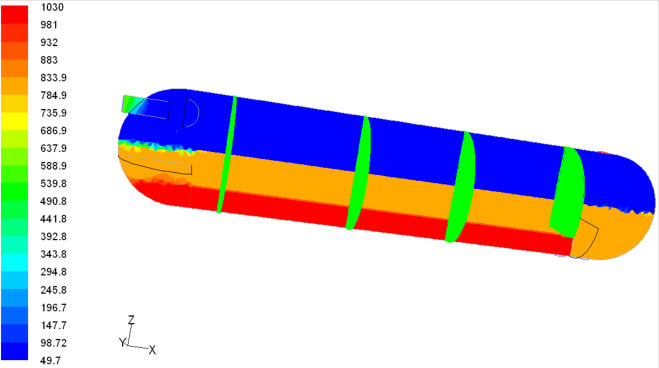
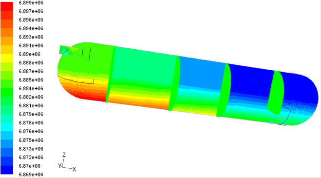
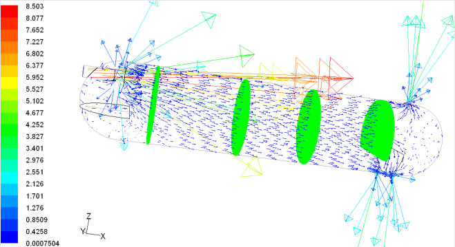
The
figures
below
show
some
of
the
produced
fluid
flow
profiles
for
the
large-scale
three-phase
separator.
There
was
excellent
agreement
between
simulated
phase
separation
behavior
and
the
empirical
observations and data gleaned from the pilot plant.
Contours of Density (kg/m
3
) in the Middle of a Large-Scale Three-Phase Separator.
Contours of Pressure (Pa) in the Middle of a Large-Scale Three-Phase Separator.
Vectors of Velocity (m/s) in the Middle of a Large-Scale Three-Phase Separator.
The
research
project
also
evaluated
the
classic
separator
design
methodologies
using
detailed
CFD
based
simulations,
and
proposed
improved
design
criteria.
In
order
to
specify
an
effective
optimum
separator,
a
useful
method
was
developed
for
estimation
of
the
droplet
sizes
used
to
calculate
realistic
separation
velocities
for
various
oilfield
conditions.
The
most
important
parameters
affecting
these
efficient
droplet
sizes
were
the
vapor
density
and
the
oil
viscosity.
In
contrast
with
classic
design
strategies,
the
CFD
simulation
results
showed
that
additional
residence
times
are
required
for
droplets
to
penetrate
through
the
interfaces.
Moreover,
the
Abraham
equation
should
be
used
instead
of
Stokes’
law
in
the
liquid-liquid
separation
calculations.
The
velocity
constraints
caused
by
re-entrainment
in
horizontal
separators
were
also
studied
via
comprehensive
CFD
simulations,
and
led
to
novel
correlations
for
the
re-entrainment
phenomenon.
Hence,
this
research
project
showed
the
benefits
that
CFD
analyses
can
provide
in
optimizing
the
design
of
new
separators
and
solving
problems
with
existing
designs.
For
more
information,
here
you find a complete and colourful Kindle version of this interesting PhD thesis.
References:
Anderson, J.D., “Computational Fluid Dynamics, The Basics with Applications”, McGraw-Hill,
1995.
Arnold, K., Stewart, M., “Surface Production Operations”, 3
rd
Edition, Elsevier, 2008.
Blezard, R.G., Bradburn, J., Clark, J.G., Cohen, D.H., Costaschuk, D., Downie, A.A., Fowler, P.,
Hassoun, L., Hunt, A.P., Kirton, D., Knight, F.I., Lach, J.R., Law, E.J., McDonald, P.A., Morrison,
A.K., Cairney, J.M., Naik, H., Sutton, W.J.E., Thompson, P., “Production Engineering”, in “Modern
Petroleum Technology”, R.A. Dawe (Ed.), 6
th
Edition, Vol. 1, Institution of Petroleum, John Wiley
& Sons, 2000.
Chin, R.W., Stanbridge, D.I., Schook, R., “Increasing Separation Capacity with New and Proven
Technologies”, Society of Petroleum Engineers, SPE-77495, 2002, 1-6.
Gerunda, A., “How to Size Liquid-Vapor Separators”, Chemical Engineering, May 4, 1981, 81-84.
Hooper, W.B., “Decantation”, Section 1.11 in “Handbook of Separation Techniques for Chemical
Engineers”, Ph.A. Schweitzer (Ed.), 3
rd
Edition, McGraw-Hill, 1997.
Lyons, W.C., Plisga, G.J. (Editors), “Standard Handbook of Petroleum and Natural Gas
Engineering”, Volume 2, Gulf Professional Publishing, 2005.
Monnery, W.D., Svrcek, W.Y., “Successfully Specify Three-Phase Separators”, Chem. Eng.
Progress, September, 1994, 29-40.
Pourahmadi Laleh, A., "CFD Simulation of Multiphase Separators", PhD Thesis, University of
Calgary, Calgary, Canada, 2010.
Sharratt, P.N., “Computational Fluid Dynamics and its Application in the Process Industries”,
Trans IChemE, 68-A, January, 1990, 13-18.
Shelley, S., “Computational Fluid Dynamics – Power to the People”, Chem. Eng. Progress, 103(4),
April, 2007, 10-13.
Sinnott, R.K., “Chemical Engineering Design” in “Coulson & Richardson’s Chemical
Engineering”, 2
nd
Edition, Butterworth-Heinemann, 1997.
Skelton, G.F., “Production”, in “Our Industry Petroleum”, Stockil, P.A. (Ed.), British Petroleum
Company Limited, 1977.
Smith, H.V., “Oil and Gas Separators”, in “Petroleum Engineering Handbook”, Bradley, H.B. (Ed),
Society of Petroleum Engineers, 1987.
Walas, S.M., “Process Vessels”, Chapter 18 in “Chemical Process Equipment Selection and
Design”, Butterworth-Heinemann, 1990.


Phase Separation Technology
Let’s
review
some
important
aspects
of
the
interesting
phase
separation technology:
The Role of Multiphase Separators
Multiphase Separator Terminology
The very first multiphase separator
The wide variety of separator designs
Phase Separation Zones
Operating Pressures and Capacities
Separator Internals
Common Operational Difficulties
CFD as a Separator Modeling Method
CFD Simulation of Multiphase Separators
The Role of Multiphase Separators
Multiphase
separators
are
one
of
the
most
prevalent
unit
operations
in
any
chemical
process.
Once
a
crude
oil
has
reached
the
surface,
the
main
purpose
of
the
surface
facilities
is
to
separate
the
produced
multiphase
stream
into
its
vapor
and
liquid
fractions.
Multiphase
separators
are
generally
the
first
process
equipment
in
an
oil
production
platform,
and
their
efficiency
influences
the
performance
of
all
downstream
equipment,
such
as
heaters,
compressors,
and
distillation
columns.
Thus,
oilfield
separators
play
a
key
role
in
the
production
capacity
of
entire
facility,
and
a
properly
sized
primary
multiphase
separator
can
increase
the capacity of the entire facility.
In
some
oilfields,
water
(brine)
is
not
produced
together
with
oil,
and
hence
only
the
gas
and
the
oil
need
to
be
separated
(two-phase
separation).
However,
usually,
three-
phase
separation
of
oil,
water,
and
gas
is
required
in
order
to
prepare
the
produced
multiphase
fluid
for
downstream
processing.
Multiphase Separator Terminology
Multiphase
separation
can
be
carried
out
through
various
oil
processing
equipment
with
the
specific
terminology
corresponding
to
each
system.
Hence,
it
is
worth
defining
the
most
important
multiphase
separators
in
the
oil
industry
before
proceeding.
The
conventional
oil
and
gas
separator,
which
is
normally
installed
on
a
production
facility
or
platform,
may
be
referred
to
as
“oil
and
gas
separator”,
“separator”,
“stage
separator”,
or
“trap”.
A
“knockout
vessel”
is
used
to
remove
either
water
or
all
liquid
from
the
well
fluid
flow.
An
“expansion
vessel”
is
the
first
stage
separator
vessel
usually
operated
at
a
low
temperature.
A
“flash
chamber”
or
“flash
vessel”
normally
refers
to
a
conventional
oil
and
gas
separator
operated
at
low
pressure
as
the
second
or
third
stage
of
the
multistage
separation.
A
“gas
scrubber”
is
an
oil
and
gas
separator
with
a
high
gas
to
liquid
ratio.
In
a
“wet-type
gas
scrubber”,
dust,
rust,
and
other
impurities
of
the
gas
phase
are
washed
using
a
bath
of
oil
or
other
liquid,
and
the
gas
flows
through
a
demister
to
further
remove
liquid
droplets
from
the
gas
stream.
A
“dry-
type
gas
scrubber”
or
“gas
filter”
is
equipped
with
demisters
and
other
coalescing
media
to
aid
in
the
removal
of
most
of
the liquid from a gas stream.
The very first multiphase separator
The
original
phase
separator
was
inclined,
very
long,
and
without
any
internal
separating
aids.
During
the
retention
time
(around
one
minute),
the
gas
and
oil
underwent
a
very
limited
separation.
Sir
Stephen
Gibson
designed
this
simple
phase
separator
and
also
the
multi-stage
separation
process.
He
was
the
first
to
put
this
process
into
operation
in
1930
at
the Haft-Kel oilfield in Iran (Skelton, 1977).
The wide variety of separator designs
A
wide
variety
of
separator
designs
and
configurations
for
multiphase
separators
in
both
vertical
and
horizontal
orientations
have
been
developed.
Various
parameters
such
as
space
and
operating
restrictions,
oilfield
variations,
potential
contaminants,
and
economic
evaluations
are
considered
in
the
design
of
a
multiphase
separation
system.
For
instance,
some
separators
may
be
equipped
with
special
impingement
internals
to
aid
the
separation
process.
The
figure
below
shows
some
different
common
designs
composed
of
“simple”,
“boot”,
“weir”,
and
“bucket
and
weir”.
These
designs
offer
a
variety
of
methods
to
control
the
interface
level
in
horizontal
three-phase
separators.
“Simple”
design
separator
can
easily
be
adjusted
to
handle
unexpected
changes
in
oil
or
water
density
or
flow
rates
(Arnold
and
Stewart,
2008).
A
boot,
typically,
is
used
when
the
water
fraction
is
not
substantial
(less
than
15-20%
of
total
liquid
by
weight),
and
a
weir
is
used
if
the
water
fraction
is
substantial
(Monnery
and
Svrcek,
1994).
The
bucket
and
weir
design
is
usually
used
when
interface
level
control
is
difficult
either
in
heavy
oil
applications
or
because
of
emulsions or paraffin problems (Arnold and Stewart, 2008
).
(a)
(b)
( c )
(d)
Different Common Designs of Horizontal Three-Phase
Separators; (a) “Simple”, (b) “Boot”, (c) “Weir”, and (d)
“Bucket and Weir”.
Phase Separation Zones
In
spite
of
the
variety
of
design
configurations
proposed
for
multiphase
separators,
the
phase
separation
process
is
accomplished
in
three
zones:
The
first
zone,
primary
separation,
uses
an
inlet
diverter
so
that
an
abrupt
change
in
flow
direction
and
velocity
causes
the
largest
liquid
droplets
to
impinge
on
the
diverter
and
then
drop
by
gravity.
In
this
zone,
the
bulk
of
the
liquid
phase
is
separated
from
the
gas
phase.
In
the
next
zone,
secondary
separation
zone,
gravity
separation
of
fine
droplets
occurs
as
the
vapor
and
liquid
phases
flow
through
the
main
section
of
the
separator
at
relatively
low
velocities
and
little
turbulence,
and
the
liquid
droplets
settle
out
of
the
gas
stream
due
to
gravity.
The
liquid
collection
section
in
the
bottom
half
of
separator
provides
the
retention
time
required
for
entrained
gas
bubbles
or
other
liquid
droplets
to
join
their
corresponding
phases
because
of
gravity
and
buoyancy.
This
section
also
provides
the
holdup
and
surge
volumes
for
safe
and
smooth
operation
of
the
separator.
Gas
flows
above
the
liquid
phase
while
entrained
small
liquid
droplets
are
again
separated
by
gravity.
The
final
zone,
coalescing
media,
is
designed
for
mist
elimination
in
which
very
fine
droplets
that
could
not
be
separated
in
the
gravity
settling
zone
are
separated
by
passing
the
gas
stream
through
a
mist
eliminator.
In
this
zone,
vanes,
wire
mesh
pad,
or
coalescing
plates
may
be
used
to
provide
an
impingement
surface
for
very
fine
droplets
to
coalesce
and
form
larger
droplets
which
can
be
separated out of gas stream by gravity.
Phase Separation Zones
Operating Pressures and Capacities
The
operating
pressure
of
separators
may
vary
from
a
high
vacuum
to
around
35
MPa
(Smith,
1987)
and
their
capacities
may
range
from
a
few
hundred
barrels
per
day
to
100000
barrels
per
day
or
more
(Skelton,
1977).
As
the
operating
pressure
of
a
separator
increases,
the
density
difference
between
the
liquid
and
gas
phases
decreases.
Therefore,
it
is
desirable
to
operate
multiphase
separators
at
as
low
a
pressure
as
is
consistent
with
other
process
conditions
and
requirements.
Most
multiphase
separators
operate
in
a
pressure range of 138 kPa to 10340 kPa (Smith, 1987).
Separator Internals
The
modern
separator
designs
have
much
higher
capacities
than
the
original
type
and
are
very
short
in
length
due
to
internals
such
as
inlet
diverters,
controls,
flow-distributing
baffles,
and
mist
extractors
which
enhance
the
separator
efficiency.
A
“weir”
design
horizontal
three-phase
separator
and
a
vertical
three-phase
separator,
both
with
the
installed
internals,
are
shown
in
the
Figures
below.
As
shown,
both
separators
are
equipped
with
inlet
diverters,
controls,
wire
mesh
demisters
and
pressure
relief
devices.
In
the
vertical
separator,
a
chimney
is
used
to
equalize
gas
pressure
between
the
lower
and
upper
sections
of
the
vessel.
Important common internals are explained as follows.
“Weir” Design Horizontal Three-Phase Separator with the
Installed Internals.
Vertical Three-Phase Separator with the Installed Internals.
Inlet Diverters
Usually
a
deflector
baffle
or
a
cyclone
is
used
as
inlet
diverter
in
the
separator.
Deflector
baffles
come
in
various
shapes
and
can
be
installed
at
different
angles.
However,
hemisphere
or
conical
designs
are
preferred
because
they
cause
fewer
disturbances
than
plates
or
angle
iron
and
reduce
re-entrainment
and
emulsion
problems
(Arnold
and
Stewart,
2008).
Cyclone
diverters
are
increasingly
used
in
oil
production
facilities
as
they
promote
foam
breaking
and
mist
elimination
while
performing
the
bulk
gas-liquid
separation
in
the
inlet
zone
(Chin
et
al.,
2002).
Hence,
cyclone
diverters
can
be
used
to
increase
the
operating
capacity of multiphase separators.
Controls
Separators
operate
at
a
predetermined
pressure
which
is
specified
by
economic
and
engineering
studies.
The
fixed
operating
pressure
in
a
separator
is
achieved
by
using
an
automatic
back
pressure
regulator
on
the
gas
outlet
line.
This
device
maintains
a
steady
operating
pressure
in
the
vessel.
The
liquid
level
controllers
and
liquid
outlet
control
valves
are
used
to
maintain
constant
oil
and
water
levels
in
the
separator.
Consequently,
the
operation
of
modern
separator systems is completely automatic.
Mist Eliminators
Droplets
with
diameters
of
100
micron
and
larger
will
generally
settle
out
of
the
gas
stream
in
most
average-sized
separators.
However,
mist
eliminators
are
usually
required
to
remove
smaller
droplets
from
the
gas
phase
(Smith,
1987).
As
95%
of
droplets
entrained
in
the
gas
stream
can
be
separated
in
economically-sized
separators
without
coalescing
media,
the
efficiency
can
be
increased
to
around
100%
by
installing
mist
eliminators
(Walas,
1990;
Sinnott,
1997;
Arnold
and
Stewart,
2008).
These
coalescing
media
can
consist
of
a
series
of
vanes,
a
knitted
wire
mesh
pad,
or
cyclonic
passages
to
remove
the
very
fine
droplets
from
the
gas
phase
by
impingement
on
a
large
surface
area
where
they
collect
and
collide
with
adjacent
droplets.
The
mechanisms
used
in
various
mist
eliminators
are
gravity
separation,
impingement,
change
in
flow
direction
and
velocity,
centrifugal
force,
coalescence,
and
filtering
(Smith,
1987).
Mist
eliminators
can
be
of
many
different
designs
exploiting one or more of these mechanisms.
The
wire
mesh
pads,
shown
below,
are
made
of
knitted
wire
mesh
and
are
installed
by
a
lightweight
support
inside
separators.
Since
the
early
1950s,
the
wire
mesh
demisters
have
been
used
in
natural
gas
processing
with
the
main
use
of
removing
fine
droplets
ranging
from
10
to
100
micron
in
diameter
from
the
gas
stream
(Smith,
1987).
Generally,
high
separation
efficiencies
at
a
low
capital
and
maintenance
cost
are
experienced
from
using
standard
wire
mesh
demisters.
The
pressure
drop
is
a
function
of
the
entrainment
load,
the
mesh
pad
design,
and
gas
velocity
but
does
not
usually
exceed
295
Pa
(Lyons
and
Plisga,
2005).
Although
pad
thicknesses
up
to
0.9
m
have
been
used,
a
pad
thickness
of
0.10
m
to
0.15
m
is
normally
sufficient
for
most
separator
applications
(Gerunda,
1981;
Walas,
1990;
Lyons
and
Plisga,
2005).
However,
the
“fouling”
tendency
of
wire
mesh
demisters
may
restrict
their
applications
to
gas
scrubbers
(Smith,
1987).
In
fact,
knitted
wire
mesh
may
foul
or
plug
from
paraffin
deposition
and
other
impurities
and
thus
reduce
separation
efficiency
dramatically
after
a
short
period
of
service.
In
such
cases,
vane-type
or
centrifugal
demisters
are used.
Wire Mesh Pad Mist Eliminator.
Vane-type
demisters,
shown
below,
are
widely
used
in
oil
and
gas
separators.
The
separation
mechanisms
used
in
most
of
vane-type
demisters
are
impingement,
change
in
flow
direction
and
velocity,
and
coalescence.
Vane-type
demisters
use
the
inertia
of
the
liquid
droplets
in
the
gas
stream
to
collect
a
film
of
liquid
on
the
vane
surface.
Vane-type
demisters
are
inexpensive
and
usually
will
not
plug
or
foul
with
paraffin
or
other
contaminants,
hence,
providing
a
good
separation
performance
under
widely
changing
field
conditions
(Smith,
1987).
Pressure
drop
across
the
vane-type
demisters
are
very
low,
ranging
from
250
Pa
to
1
kPa
(Smith,
1987).
Vane-Type Mist Eliminator.
Common Operational Difficulties
The
most
common
factors
which
can
reduce
separator
performance
are
very
high
or
very
low
liquid
level,
level
control
failure,
improper
design,
damaged
vessel
internals,
foam,
vortex
formation
in
liquid
outlet
zones,
plugged
liquid
outlets,
and
exceeding
the
design
capacity
of
the
vessel (Arnold and Stewart, 2008).
The
common
approaches
used
for
improving
the
separator
performance
in
difficult
cases,
as
proposed
by
Blezard
et
al.
(2000),
are
increasing
droplet
size
of
dispersed
phase
(e.g.,
by
promoting
coalescence),
inducing
a
high
acceleration
on
droplets
(e.g.,
by
using
centrifugal
force),
increasing
the
difference
between
fluid
densities
(e.g.,
by
introducing
diluents),
and
decreasing
the
viscosity
of
the
liquid
phases
(e.g.,
by
heating).
Some
of
these
approaches
may
be
combined
to
overcome
a
difficult
separation
task.
In
the
following,
some
different
measures
taken
for
operating
foamy, emulsified, or contaminated crude oils are outlined.
Foamy
crude
oils
hinder
liquid
level
control
and
also
reduce
the
separation
space
of
the
separator.
To
improve
the
separator
performance,
it
is
usually
advantageous
to
inject
a
silicon
defoaming
agent
into
the
foamy
oil
stream
(around
1x10
-6
m
3
for
1
m
3
of
oil)
before
it
enters
the
separator
(Skelton,
1977).
This
agent
breaks
up
the
foam
and
keeps
oil
from
being
carried
over
by
the
gas
phase,
leading
to
an
effective
increase
in
the
capacity
of
the
separator.
The
other
approaches
that
assist
in
breaking
the
foam
are
settling,
baffling,
heat,
and
centrifugal
force
(Smith,
1987).
For
separators
suffering
from
liquid
carryover
while
processing
foamy
crude
oils,
or
glycols,
amines,
and
similar
materials
(with
high
foaming
tendency),
a
dual
mist
eliminator
system
composed
of
a
vane-type
demister
at
a
lower
level
and
a
wire
mesh
pad
at
higher
level
with
a
gap
of
0.15
to
0.30
m
between them is usually used (Lyons and Plisga, 2005).
The
other
separation
difficulty
is
caused
by
thoroughly
emulsified
oil.
The
water
phase
enters
the
bottom
of
the
producing
well
and
usually
breaks
up
into
fine
droplets
on
its
way
to
the
surface.
These
fine
droplets
form
an
emulsion
with
the
oil
phase
which
can
lead
to
a
fully
emulsified
phase.
Separation
of
the
thoroughly
emulsified
phase
is
extremely
difficult,
and
it
is
often
recommended
that
as
much
of
the
water
as
possible
be
removed
at
the
well
head
(Skelton,
1977).
This
treatment
is
done
by
processing
the
crude
oil
through
a
large
vessel
(long
retention
time)
which
would
allow
the
larger
water
droplets
to
settle
out.
If
further
treatment
of
the
separated
oil
phase
is
necessary,
the
oil
phase
may
be
heated
to
help
break
down
the
emulsion.
Usually,
a
surface
tension
reducing
chemical
is
also
added
to
enhance
the
treatment.
Generally
the
combined
application
of
heat
and
chemicals
is
sufficient
to
reduce
the
water
and,
consequently,
the
salt
content
of
the
oil
phase
to
an
acceptable
level
(Skelton,
1977).
However,
sometimes
the
use
of
an
electrical
coalescing
media
may
be
necessary
to
achieve
specification
level
of
oil
product.
In
this
treatment
method,
the
oil-water
stream
is
exposed
to
an
electrical
field
which
agitates
the
water
droplets
and
causes
them
to
collide
and
coalesce
into
larger
droplets
and
then
to
settle
out
of
the
oil
phase.
The
resultant
water
concentration
in
the
effluent
oil
stream is usually less than 0.5% (Blezard et al., 2000).
Another
emulsion
problem
is
experienced
when
some
very
fine
particles
cause
a
stabilized
rag
layer
at
the
oil-water
interface.
In
order
for
the
separator
to
operate
properly,
the
rag
layer
must
be
regularly
broken
or
removed.
For
this
purpose,
some
techniques
such
as
filtration,
heating,
and
chemical injection are used (Hooper, 1997).
Contaminated
crude
oils
are
also
difficult
to
process.
The
most
common
contaminants
are
sand,
silt,
mud,
and
salt.
Medium-sized
sands
in
small
quantities
can
be
removed
by
an
oversized
vertical
settler.
The
residue
should
be
removed
periodically
by
draining
from
the
vessel
bottom.
Salt
may
be
removed
by
washing
the
oil
with
water
and
then
separating
the salty water from the oil phase.
CFD as a Separator Modeling Method
Computational
Fluid
Dynamics
(CFD)
is
inherently
connected
with
the
“fluid”
concept.
It
is
interesting
that
this
“fluid”
concept
can
still
be
defined
as
Isaac
Newton
proposed
more
than
300
years
ago
in
the
following
elegant
way:
“A
fluid
is
any
body
whose
parts
yield
to
any
force
impressed
on
it,
and
by
yielding,
are
easily
moved
among
themselves.”
The
physical
features
of
any
fluid
flow
are
governed
by
three
fundamental
physical
principles:
mass
is
conserved,
Newton’s
second
law
applies,
and
energy
is
conserved.
These
fundamental
physical
principles
can
be
represented
in
terms
of
mathematical
equations,
generally
in
the
form
of
integral
equations
or
partial
differential
equations.
Computational
fluid
dynamics
is
the
art
of
replacing
the
integrals
or
the
partial
derivatives
in
these
equations
with
their
equivalent
discretized
algebraic
forms.
These
discretized
algebraic
equations
are
then
solved
to
provide
numbers
for
the
flow
field
values
at
discrete
points
in
time
and/or
space.
Therefore,
in
contrast
with
an
analytical
solution,
the
final
product
of
a
CFD
modeling
is
a
collection
of
numbers.
CFD
solutions
generally
require
the
iterative
manipulation
of
many
thousands,
even
millions,
of
numbers.
This
task
is
obviously
impossible
without
the
aid
of
a
high-speed
digital
computer
which
accelerated
the
practical
development
of
CFD.
The
historical
development
of
CFD,
as
reviewed
by
Anderson
(1995),
indicates
that
before
1970,
there
was
no
CFD
in
the
way
that
we
think
of
it
today,
and
although
there
was
CFD
in
1970,
the
storage
and
speed
capacity
of
computers
limited
all
practical
solutions
essentially
to
two-dimensional
flow
problems.
However,
by
1990,
this
story
had
changed
dramatically.
In
today’s
CFD
modeling
applications,
three-dimensional
flow
field
solutions
are
abundant
and
such
solutions
are
becoming
more
and
more
prevalent
within
industry
and
government
facilities.
Indeed,
some
computer
programs
for
the
calculation
of
three-dimensional
flows
have
become
industry
standards,
resulting
in
their
use
as
a
tool
in
the
design
process.
In
short,
CFD,
along
with
its
role
as
a
research
tool,
is
playing
an
increasingly
stronger
role
as
a
design tool.
The
high
storage
capacities
and
calculation
speed
of
present
computers
and
advanced
techniques
devised
in
modern
CFD
solvers
have
culminated
in
today’s
common
use
of
commercial
software
packages
for
CFD
simulation
of
industrial
equipment.
Currently,
CFD
software
packages
are
routinely
used
to
modify
the
design
and
to
improve
the
operation
of
most
types
of
chemical
process
equipment,
combustion
systems,
flow
measurement
and
control
systems,
material
handling
equipment,
and
pollution
control
systems
(Shelley,
2007).
For
implementation
of
a
CFD
simulation
using
a
commercial
software
package,
the
geometry
of
the
object
of
interest
is
specified
(with
a
computer
aided
design
drawing
of
the
object)
and
the
corresponding
discretized
grid
system
is
created
using
a
mesh-generation
tool.
For
mesh
generation,
present
software
tools
provide
some
predefined
building
units
in
a
variety
of
forms
such
as
tetrahedral,
pyramidal,
hexahedral,
and
recently,
polyhedral
blocks.
However,
generating
a
high
quality
mesh
for
the
system
is
still
one
of
the
most
technical
and
time-consuming
phases
in
any
CFD
based
analysis.
After
preparing
the
grid
system,
the
initial
and
boundary
conditions
of
the
problem
are
specified,
and
the
CFD
parameters
are
set.
Finally,
the
CFD
software
proceeds
with
the
iterative
process
of
solving
the
fundamental
equations
for
fluid
flow.
As
noted,
once
a
converged
solution
is
achieved,
CFD
simulation
output
is
a
collection
of
numbers
which
correspond
to
the
defined
points
in
space
or
time.
In
order
to
visualize
these
CFD
simulation
results
and
obtain
qualitative
aspects
of
the
system,
the
post-processing
tool
of
CFD software is used.
CFD
complements
the
approaches
of
pure
theory
and
pure
experiment
in
the
analysis
and
solution
of
fluid
dynamic
problems.
Although
CFD
will
probably
never
completely
replace
either
of
these
approaches,
it
helps
to
interpret
and
understand
the
results
of
theory
and
experiment.
It
should
be
noted
that
suitable
problems
for
CFD
often
involve
predictions
outside
the
scope
of
published
data,
where
experimental
studies
are
too
expensive
or
difficult
or
where
the
development
of
an
insight
is
required
(Sharratt,
1990).
Therefore,
CFD
is
primarily
an
insight
tool
which
is
useful
for
understanding
the
important
features
of
a
system
and
for
elucidating
and
solving
some
system
uncertainties
and
problems.
CFD Simulation of Multiphase Separators
In
our
recent
research
project,
we
applied
Computational
Fluid
Dynamics
(CFD)
based
simulation
to
model
multiphase
separators.
In
order
to
capture
both
macroscopic
and
microscopic
aspects
of
multiphase
separation
phenomenon,
an
efficient
combination
of
two
multiphase
models
was
used.
The
Volume
of
Fluid
(VOF)
model
was
used
to
simulate
the
phase
behavior
and
fluid
flow
patterns,
and
the
Discrete
Phase
Model
(DPM)
was
used
to
model
the
movement
of
fluid
droplets
injected
at
the
separator
inlet.
The
“particle
tracking”
based
simulation
of
the
multiphase
separation
process
was
the
key
aspect
of
this
research
project,
and
the
developed
model
did
provide
high-quality
visualization of multiphase separation process.
The
research
project
involved
the
CFD
simulation
of
four
pilot-plant-scale
two-phase
separators
and
one
industrial
scale
three-phase
separator,
including
all
the
installed
internals.
The
figures
below
show
some
of
the
produced
fluid
flow
profiles
for
the
large-scale
three-phase
separator.
There
was
excellent
agreement
between
simulated
phase
separation
behavior
and
the
empirical
observations
and
data
gleaned from the pilot plant.
Contours of Density (kg/m
3
) in the Middle of a Large-Scale
Three-Phase Separator.
Contours of Pressure (Pa) in the Middle of a Large-Scale
Three-Phase Separator.
Vectors of Velocity (m/s) in the Middle of a Large-Scale
Three-Phase Separator.
The
research
project
also
evaluated
the
classic
separator
design
methodologies
using
detailed
CFD
based
simulations,
and
proposed
improved
design
criteria.
In
order
to
specify
an
effective
optimum
separator,
a
useful
method
was
developed
for
estimation
of
the
droplet
sizes
used
to
calculate
realistic
separation
velocities
for
various
oilfield
conditions.
The
most
important
parameters
affecting
these
efficient
droplet
sizes
were
the
vapor
density
and
the
oil
viscosity.
In
contrast
with
classic
design
strategies,
the
CFD
simulation
results
showed
that
additional
residence
times
are
required
for
droplets
to
penetrate
through
the
interfaces.
Moreover,
the
Abraham
equation
should
be
used
instead
of
Stokes’
law
in
the
liquid-liquid
separation
calculations.
The
velocity
constraints
caused
by
re-entrainment
in
horizontal
separators
were
also
studied
via
comprehensive
CFD
simulations,
and
led
to
novel
correlations
for
the
re-
entrainment
phenomenon.
Hence,
this
research
project
showed
the
benefits
that
CFD
analyses
can
provide
in
optimizing
the
design
of
new
separators
and
solving
problems with existing designs.
For
more
information,
here
you
find
a
complete
and
colourful Kindle version of this interesting PhD thesis.
References:
Anderson, J.D., “Computational Fluid Dynamics, The Basics
with Applications”, McGraw-Hill, 1995.
Arnold, K., Stewart, M., “Surface Production Operations”, 3
rd
Edition, Elsevier, 2008.
Blezard, R.G., Bradburn, J., Clark, J.G., Cohen, D.H.,
Costaschuk, D., Downie, A.A., Fowler, P., Hassoun, L., Hunt,
A.P., Kirton, D., Knight, F.I., Lach, J.R., Law, E.J., McDonald,
P.A., Morrison, A.K., Cairney, J.M., Naik, H., Sutton, W.J.E.,
Thompson, P., “Production Engineering”, in “Modern
Petroleum Technology”, R.A. Dawe (Ed.), 6
th
Edition, Vol. 1,
Institution of Petroleum, John Wiley & Sons, 2000.
Chin, R.W., Stanbridge, D.I., Schook, R., “Increasing
Separation Capacity with New and Proven Technologies”,
Society of Petroleum Engineers, SPE-77495, 2002, 1-6.
Gerunda, A., “How to Size Liquid-Vapor Separators”,
Chemical Engineering, May 4, 1981, 81-84.
Hooper, W.B., “Decantation”, Section 1.11 in “Handbook of
Separation Techniques for Chemical Engineers”, Ph.A.
Schweitzer (Ed.), 3
rd
Edition, McGraw-Hill, 1997.
Lyons, W.C., Plisga, G.J. (Editors), “Standard Handbook of
Petroleum and Natural Gas Engineering”, Volume 2, Gulf
Professional Publishing, 2005.
Monnery, W.D., Svrcek, W.Y., “Successfully Specify Three-
Phase Separators”, Chem. Eng. Progress, September, 1994,
29-40.
Pourahmadi Laleh, A., "CFD Simulation of Multiphase
Separators", PhD Thesis, University of Calgary, Calgary,
Canada, 2010.
Sharratt, P.N., “Computational Fluid Dynamics and its
Application in the Process Industries”, Trans IChemE, 68-A,
January, 1990, 13-18.
Shelley, S., “Computational Fluid Dynamics – Power to the
People”, Chem. Eng. Progress, 103(4), April, 2007, 10-13.
Sinnott, R.K., “Chemical Engineering Design” in “Coulson
& Richardson’s Chemical Engineering”, 2
nd
Edition,
Butterworth-Heinemann, 1997.
Skelton, G.F., “Production”, in “Our Industry Petroleum”,
Stockil, P.A. (Ed.), British Petroleum Company Limited,
1977.
Smith, H.V., “Oil and Gas Separators”, in “Petroleum
Engineering Handbook”, Bradley, H.B. (Ed), Society of
Petroleum Engineers, 1987.
Walas, S.M., “Process Vessels”, Chapter 18 in “Chemical
Process Equipment Selection and Design”, Butterworth-
Heinemann, 1990.